Determination of Modulus of Rigidity
using Barton's Apparatus (Vertical)
An interactive laboratory workspace for studying the torsion of a cylindrical rod and determining its modulus of rigidity.
Objective
Section 01Aim
To determine the modulus of rigidity of the material of a cylindrical rod using Barton's apparatus in the vertical arrangement.
Learning Objectives
After completing this experiment, students will be able to:
- Understand the relationship between torque, angular twist, and torsional rigidity.
- Explain the working principle of Barton's apparatus in the vertical configuration.
- Measure the dimensions of the rod and the effective length of the suspended rod.
- Measure the angular twist produced by known couples.
- Determine the modulus of rigidity using the appropriate torsion formula.
- Verify that the applied torque is proportional to the angle of twist within the elastic limit.
- Estimate experimental uncertainties and identify possible sources of error.
- Identify precautions and sources of error in torsion experiments.
After completing this virtual experiment, learners will be able to:
- Understand modulus of rigidity as a measure of resistance to shear deformation.
- Explore how an applied couple produces angular twist in a vertical rod.
- Use the simulation to obtain twist readings for different applied loads.
- Analyze the torque–twist relationship within the elastic limit.
- Determine the modulus of rigidity from simulated observations.
- Interpret observations using tables, graphs, and calculations.
- Evaluate how rod dimensions and measurement uncertainty affect the result.
- Connect torsional rigidity with shafts, axles, and mechanical power transmission.
Theory
Section 021. Modulus of Rigidity
When a cylindrical rod is twisted within its elastic limit, it develops an internal restoring torque. The modulus of rigidity, denoted by η (or G), is the ratio of shear stress to shear strain:
A larger value of η indicates greater resistance to torsional deformation.
2. External Couple in Barton’s Apparatus
In Barton’s apparatus, a pulley of diameter D is attached to the rod. Equal masses M are suspended by strings wound around opposite sides of the pulley. Each mass produces a tangential force Mg; the two equal and opposite forces form a couple.
Thus, the externally applied torque is:
Here, g is the acceleration due to gravity and D is the distance between the lines of action of the two forces.
3. Restoring Couple and the Fixed-End Correction
For a uniform solid cylindrical rod of radius r, the restoring torque for a length L twisted through θ radians is given by the torsion equation:
- η = modulus of rigidity
- r = radius of the rod
- L = length of the rod segment under torsion
- θ = angle of twist in radians
The clamp at the fixed end may undergo a small amount of slip or twist. Barton’s apparatus eliminates this fixed-end error by measuring the twist at two points along the rod. If the pointers are at distances l1 and l2 from the fixed end, and their readings are θ1 and θ2, respectively, then the relevant segment has length l2 − l1 and twist θ2 − θ1.
4. Modulus of Rigidity
At equilibrium, the external and internal torques are equal:
Therefore, when the angular readings are in radians:
5. Using Readings in Degrees
The circular scales usually give angles in degrees. Convert the measured difference before using the torsion equation:
Substitution gives the working formula:
If the apparatus specifies the pulley radius R instead of its diameter, use D = 2R. The equivalent expression is:
All lengths must be in metres, masses in kilograms, and the final value of η is obtained in pascals (N/m2).
Apparatus Required
Section 03Apparatus
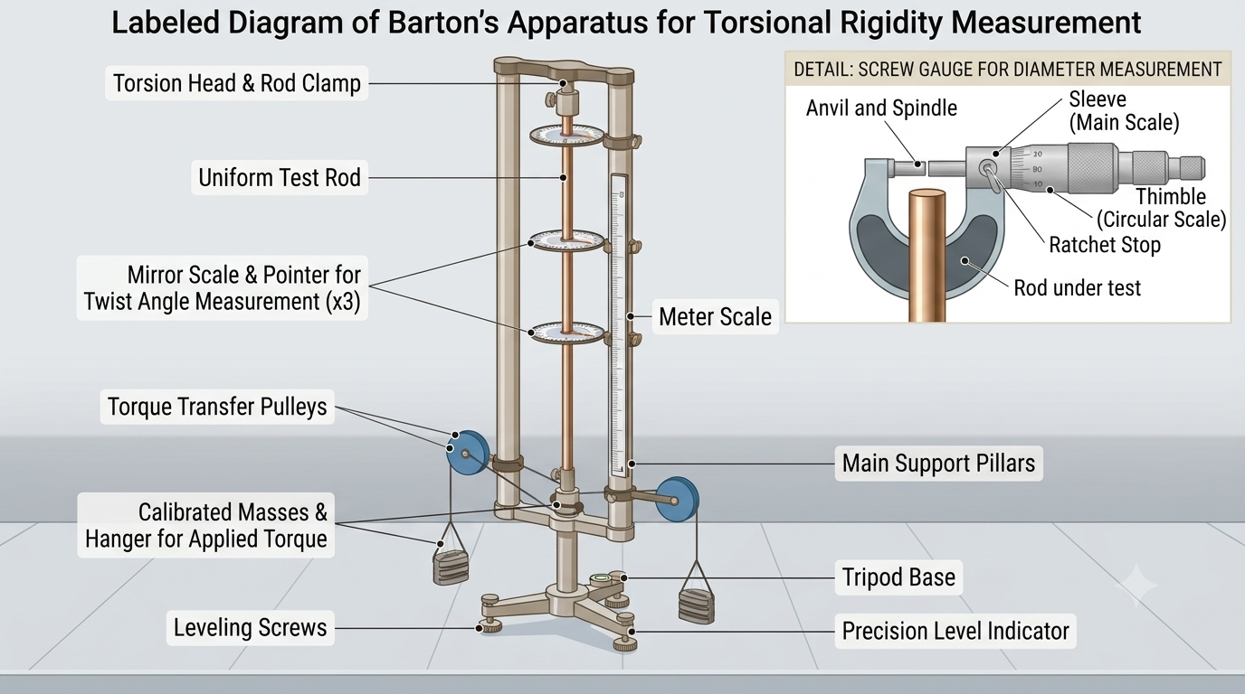
- Barton’s apparatus arranged vertically
- Uniform cylindrical rod with torsion head
- Load carriers and slotted weights
- Graduated circular scale and pointer
- Meter scale
- Screw gauge for measuring the rod diameter
- Spirit level and leveling arrangement
Procedure
Section 04Procedure (Real Experiment)
- Fix the cylindrical rod vertically in Barton’s apparatus. Check that the rod, torsion head, and pulley are properly aligned along the same axis.
- Determine the least count and zero error of the screw gauge. Measure the rod diameter at several positions and in different orientations, then calculate the mean diameter and the mean radius r.
- Determine the least count and zero error of the Vernier calipers. Measure the diameter of the cylindrical pulley or drum and record it as D.
- With no load applied, select two graduated scales and their corresponding pointers. Fix them at two different positions along the rod, set both pointers to the zero reading, and measure the separation l2 − l1 between the two scales.
- Apply equal masses to the two pans in small, known steps, starting from 0 g and increasing by 500 g per pan. Allow the rod to come to rest before taking each reading.
- For each applied mass, record the deflections θ1 and θ2 shown by pointers 1 and 2, respectively, on both sides of each circular scale.
- Continue the observations for equal masses from 0 to 2 kg per pan in steps of 0.5 kg. Keep the load within the elastic limit of the rod.
- Remove the masses in the same steps and record the corresponding readings during unloading.
- For each mass, take the mean of the loading and unloading readings separately for θ1 and θ2, using the readings from both sides of the scales as appropriate.
- For a selected mass, such as 1.5 kg per pan, calculate the angle of twist between the two pointers as θ = θ2 − θ1. Use the magnitude of this difference if only the deflection magnitude is required.
- Calculate the modulus of rigidity using the degree-based working formula η = 360MgD(l2 − l1)/[π2r4(θ2 − θ1)deg], where M is the mass on each pan.
- Repeat the calculation for the remaining observations and report the mean value of η in N/m2.
Procedure (Virtual Experiment)
Open the Simulation section before beginning the following measurements.
1. Measurement of the Radius (r) of the Solid Cylindrical Rod
- Open Simulation-I. A virtual screw gauge and the cross-section of the solid cylindrical rod will be displayed.
- Determine the least count and zero error of the screw gauge.
- Open the screw-gauge jaws by dragging the thimble.
- Drag the rod towards the jaws of the screw gauge and release it.
- Close the jaws gently until they just touch the rod, and note the screw-gauge reading.
- Repeat the measurement 3–4 times at different positions along the rod.
- Record all observations in the observation table titled Measurement of the Radius (r) of Solid Cylindrical Rod.
- Apply the required zero-error correction and calculate the mean radius r of the rod.
2. Measurement of the Drum Diameter (D)
- Open Simulation-II. A virtual Vernier caliper and the cross-section of the cylindrical drum will be displayed.
- Determine the least count and zero error of the Vernier caliper.
- Open the Vernier-caliper jaws by dragging the Vernier scale.
- Drag the drum towards the jaws of the Vernier caliper and release it.
- Close the jaws gently until they just touch the drum, and note the Vernier-caliper reading.
- Repeat the measurement 3–4 times at different positions on the drum.
- Record all observations in the observation table titled Measurement of Diameter (D) of Drum.
- Apply the required zero-error correction and calculate the mean diameter D of the drum.
3. Measurement of the Modulus of Rigidity Using Barton’s Apparatus (Vertical)
- Open Simulation-III. Barton’s apparatus is displayed in the right panel and the available controls are displayed in the left panel.
- Level the apparatus horizontally using the Level 1 and Level 2 sliders.
- Set the positions of the scales and pointers along the rod using the Scale 1, Scale 2, and Scale 3 sliders. The corresponding positions are shown next to their respective sliders.
- Apply equal masses to the two pans in small, known steps using the Load slider. Start from 0 g and increase the mass by 500 g per pan at each step.
- For each selected scale and pointer, note the corresponding deflections θ1 and θ2 from Scale 1 Reading, Scale 2 Reading, and Scale 3 Reading.
- For increasing and decreasing equal masses from 0 to 2 kg per pan, in steps of 0.5 kg, record the corresponding values of θ1 and θ2.
- Enter all observations in the observation table for the Measurement of the Modulus of Rigidity.
- Use the recorded data and the Ink Overlay Tool in the Result and Analysis section to calculate the modulus of rigidity.
- Enter the calculated value of η in the provided input box.
- Download the completed experiment as a PDF by clicking the Export PDF button.
Simulation
SimulationObservation Table
Section 06Table 1: Measurement of the radius (r) of cylindrical rod
Table 2: Measurement of diameter (D) of the Drum
Table 3: Measurement of the Modulus of Rigidity Using Barton’s Apparatus
Result and Analysis
Section 07Calculation on freehandTool
Modulus of Rigidity Using Barton’s Apparatus – MCQs
Select the most appropriate answer.